Laser Cutting: Difference between revisions
No edit summary |
No edit summary |
||
| Line 76: | Line 76: | ||
<gallery> | <gallery> | ||
File:Fushion 360 Inspect options.png|How to display component colors using the inspect menu. | File:Fushion 360 Inspect options.png|How to display component colors using the inspect menu. | ||
File:5. Defining the size.png| | File:5. Defining the size.png|Define your size, switching between height and width with [Tab➡] key | ||
</gallery> | </gallery> | ||
[[ | [[Category:Fabrication]] | ||
Revision as of 10:22, 20 March 2024

Laser cutters use high-power laser system which allows for precise and fast processing of projects. It is still important to carefully check any files with the technical team to ensure a complete understanding of the timeframes of any work.
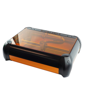
The Makerspace has Emblaser 2, small desktop laser cutter for small projects and the Trotec SP500 large format laser cutter.
Specifications
| Type | Quantity | Dimensions | Materials | Risk Assessment |
|---|---|---|---|---|
| SP 500 | 1 | 1245 mm x 710 mm | Strawboard, Plywood | None, but induction required. |
| Emblaser 2 | 10 | 500mm x 300mm | Strawboard, Plywood | None, but induction required. |
Emblaser 2 This equipment is watched over by the user for the entirety of the printing process. In the event of an emergency, please signal to the nearest technician.
File Preparation

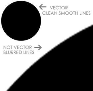
1. Ensure you are using vector files
- Vector files need to be DRAWN in the vector program rather than just imported or pasted in there. Also opening a vector file in a raster file program, such as Photoshop, will convert it to a raster image.
2. Ensure correct use of colours
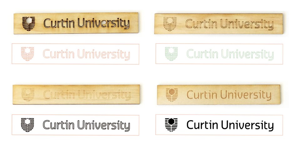
To process any file, it is required that the PDF only have the following colours:
- Cut = Pure RGB Red (HEX #FF0000 / RGB (255, 0, 0))
- Vector engrave = Pure RGB Green (HEX #00FF00 / RGB (0, 255, 0))
- Raster engrave = RGB Blue (HEX #0000FF / RGB (0, 0, 255))
3. Save as PDF
- PDF format is the only file received in the Makerspace to process any laser cutting job. It is lightweight and avoids the importing of unnecessary information such as CAD. Ensure that you have made your file as a PDF.
4. Use correct naming structure
- StudentID_MaterialThickness_MaterialSize.PDF

Setting up files

Autodesk Fusion 360
Autodesk Fusion 360 combines CAD, CAM, CAE, and PCB into a single, integrated cloud software platform. It includes all the tools that you need to go from design to manufacturing, seamlessly.
Laser Cutting Setup
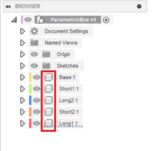
The golden rule in Fusion is that you make sections of your models as components. This approach involves organising different sections of a model as separate components, each containing essential data such as sketch information, bodies, and origin planes. This concept can be likened to layers in software applications like AutoCAD or Photoshop.
Example of component-based modelling
Let's say you want to laser cut a 3mm Polar ply box with connecting finger joints. Using the inspect menu, you can select "Display Component Colors" to visually seen each component with a distinct colour ID. To prepare the design for laser cutting:
- Selecting the top-level component
- Creating a new sketch
- Draw a rectangle using the create menu or simply hit the [R] key
- Select Center Point rectangle
- Define your size, switching between height and width with [Tab➡] key
- Hit enter and then finish sketch
- Ensure the plane is at the bottom of your model.
- Select Arrange in Modify menu with all the components selected, or select them individually afterward.
- Make sure all components are selected and appear in Arrange options.
- Finally, select envelope on the plane to arrange the objects flat.
-
How to display component colors using the inspect menu.
-
Define your size, switching between height and width with [Tab➡] key

![Define your size, switching between height and width with [Tab➡] key](/images/thumb/8/8a/5._Defining_the_size.png/120px-5._Defining_the_size.png)